Generator Components Section 1
ACES Introduction to Generator Components
This section will provide an overview of functionality of components encountered throughout the steam generator. The information presented in this section is a general compilation of possible components on a steam generator. The appearance of many components depends on the style and setup of the generator.
Air Compressor
Includes: Instrument Air Pressure Switch
The air compressor supplies pressurized air for all pneumatic controls and instrumentation on the generator. The air compressor may be located on the generator skid or at a separate location in which case pressurized air piping will be installed and run to each component. In most cases the air compressor is located near the operator platform around the feedwater pump and motor. However, ACES generators locate the compressor underneath the convection section in order to free up space around the operator platform.
The air compressor is made up of two parts; the motor and the cylinder. The motor electrically drives the attached sheave (slotted wheel that the drive belts sit in) which rotates the larger cylinder sheave. This drives the pistons inside the cylinder in and out creating a vacuum. As each piston retracts, the voided space gets filled with air from around the compressor, which is brought in through the inlet valve. When the piston extends, that same air is compressed and given enough strength to push through the discharge valve while simultaneously holding the inlet valve shut. From there the air enters a storage tank which increases in pressure as the tank fills. Each compressor will have a setpoint pressure. Once the tank pressure reaches the setpoint, the compressor turns off. As air is used by instruments, the pressure will decrease and the compressor will turn on to maintain the tank setpoint pressure. Downstream of the air compressor will be the instrument air pressure switch. This switch will be on the piping before air is split off into the inlet lines for pneumatic devices and ensures there is adequate pressure for these devices to function properly.


Air Compressors
Atomization; Air and Steam
Includes:
- Air Atomization Check Valve (1)
- Air Atomization Pressure Regulator (2)
- Air Atomization Control Valve (3)
- Air Atomization Pressure Transmitter (4)
- Atomization Pressure Switch (Optional)
- Steam Atomization Check Valve (5)
- Steam Atomization Pressure Regulator (6)
- Steam Atomization Control Valve (7)
- Atomization Pressure Transmitter (8)
- Steam Atomization High Stage Pressure Control Valve (Optional)
- Steam Atomization High Stage Pressure Transmitter (Optional)
- Steam Atomization Knockout Drum (9)
- Steam Atomization Knockout Drum Pressure Safety Valve (10)

Atomization Components

Steam Atomization Knockout Drum
Atomization is necessary, and will only be installed, when burning any oil or other heavy liquid fuel. Fuel is atomized so that it will readily mix with the surrounding air and burn fully and quickly. Without atomization, the solid stream of fuel would take a long time to completely burn or, if the flow rate were high enough, not burn at all and could accumulate on the radiant floor and start a fire. A steam generator will use both air and steam atomization while running. Initially air atomization is required since steam is not yet being produced. Compressed air will pass through a check valve, pressure regulator, and solenoid control valve. A pressure transmitter will be attached before the regulator to monitor the air pressure entering the regulator. Once the steam has reached quality for an extended period of time, the air atomization will wane off and steam atomization with take over.
During steam atomization, part of the steam exiting the discharge separator will be split off into smaller piping. This piping will continue through a knockout drum where the steam will be separated from any existing liquid water. The steam will exit the knockout drum at 100% quality and travel through a manual shutoff valve, check valve, pressure regulator, and solenoid control valve.
A pressure transmitter will be present on the piping between the air and steam lines. A high- and low-pressure switch can also optionally be installed. For steam generators set up to run at high pressures, there may be an additional high stage pressure control valve to reduce the pressure before the steam enters the knockout drum. In this case, an additional pressure transmitter will also be present to measure the pressure after the control valve. Both the steam and air piping will connect to one pipe which will go to the burner. This piping attaches to a plate on the side of the burner that also has an inlet for the fuel being atomized.

Burner Atomization Plate
Burner
Includes:
- Burner Flame Sight Port
- UV Scanner
The burner takes in air from the combustion blower and mixes it with fuel from the Pilot or Main Gas line to create heat from combustion. This creates a large flame inside the Radiant Section that promotes radiant heat transfer to the water inside of the pipes running through the Radiant Section. The flame can be as large as 4’ in diameter and 18’ feet long or longer depending on the radiant shell length and the burner. The burner will modulate based off of temperature, quality, and when equipped with an O2 sensor, oxygen concentration in the exhaust stack.
For most generators the desired O2 concentration is 2-4% in the exhaust stack. A lower concentration promotes the forming of undesirable products like CO and NO due to a lack of oxygen atoms needed for creating CO2. Too high of a concentration of air decreases the efficiency of the generator. More excess air means more N2 is traveling through the burner. N2 acts as an inert gas during combustion and consumes heat that leaves the generator through the exhaust stack. Heat that could have been used for heating water is instead used for heating the N2 thereby reducing the efficiency of the generator.
Additional features connected to the burner assembly include the burner flame sight port and the UV sensor. The sight port is attached to the back of the combustion blower chamber and gives a straight sightline through the burner for viewing the flame. The UV sensor is typically mounted on the top of the burner towards the burner throat and is used for monitoring the flame signal.

Burner Sight Port and UV Sensor
Check Valve
Check valves are self-contained valves that allow a fluid to pass through in only one direction and are used throughout the water, steam, and air piping on a steam generator. This type of valve relies solely on the flow of the fluid for it to open and close. As flow increases, the pressure against the disc also increases. This pressure will rise until it reaches the cracking pressure at which point the disc will move and allow the fluid to pass through. If the flow rate becomes too low or reverses, the disc will seal the valve.
Check valves come in many styles but the two most common are swing check and lift check. A swing check valve has a disc attached to a hinge allowing it to swing up into the valve body once the cracking pressure is reached. A lift check valve has a disc which sits in a seat. As the flow rate in the valve increases, the force of the fluid presses against the disc and raises it allowing flow to continue through the valve. A third variant of the check valve used on a steam generator is the stop-check valve (also called a stop-globe valve). This valve is a combination of a globe valve and check valve. In a normal globe valve, the valve stem is permanently affixed to the globe disc while in a stop-check valve the stem head floats in the globe disc. This style of check valve has two purposes: isolate or regulate flow and prevent reverse flow. Stop-check valves are used as the pre-heater and bypass control valves on the outlet of the convection section piping.


Swing Check Valve


Lift Check and Stop-Check Valves
Combustion Blower
Includes:
- Burner Air Intake
The air intake is located on the operator’s platform above the burner and is the inlet piping for the combustion blower. The air intake is typically covered with a cap to deter water and other objects from entering the combustion blower. The combustion blower and motor make up the back half of the burner assembly and is where the air intake attaches to. As the blower motor spins the combustion blower, ambient air is drawn in from the air intake and expelled through the burner where it mixes with fuel to promote a more ideal combustion environment. The amount of air flow is regulated by a VFD, damper, or both. The combination of these regulators increases the generator’s efficiency and can reduce the production of unwanted combustion byproducts like CO, NO, and NO2.
Combustion Blower and Air Intake
Fuel Gas
Includes:
- Burner Diffuser
- Fuel Distribution Ring
Air enters the combustion blower and travels through the body of the burner. At the end of the burner throat, where the burner bolts to the generator, there will be a metal ring. This is the fuel distribution ring. Fuel gas exits this ring through fuel ports where it meets the air and they collectively travel through a diffuser plate. These ports can have covers on them to limit the BTU input of the burner by limiting the amount of fuel that passes through. The diffuser plate is a circular assembly of metal arms with small holes in them that extend in front of the exit ports on the fuel distribution ring, and is used to promote mixing of the fuel and air.
The fuel distribution ring will not be used until the step to light the main flame is reached. Prior to this, a separate air stream will connect to the pilot fuel line and the mixture will pass by the spark ignitor and through the flame extender. Initially the flame will be small since the burner will be running off of only the gas flowing through the Pilot line. Once the control system determines the pilot flame is lit, the Main line will open and flood the distribution ring with gas. After the main flame is lit, the Pilot line will close and fuel and air will be modulated to reach and maintain quality. See Fuel Gas Main Train and Fuel Gas Pilot Train for additional information on the Main and Pilot fuel lines, respectively.


Diffuser and Fuel Distribution Port

Pilot Air Supply
Fuel Oil
Includes:
- Fuel Nozzle
- Burner Gun
- Burner Gun Heater
Air enters the combustion blower and travels through the body of the burner. Like with fuel gas, there will be a diffuser plate at the end of the burner throat. Oil and air or steam will be mixed upon entering the burner atomization plate as shown in Burner Atomization Plate. The mixture will enter the burner gun and exit through the fuel nozzle, which is used to atomize the fuel. The fuel nozzle exits in the middle of the diffuser plate so the atomized fuel immediately mixes with the incoming air.


Fuel Nozzle
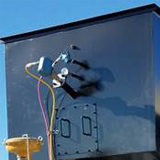
Burner Hinge Switch
The burner hinge switch is typically located on the top side of the burner where it connects to the burner throat or where it swings apart for maintenance. This is a normally open limit switch used for keeping the generator from running while the burner is out of its normal operating position. The switch is a hard metal casing, which contains the wiring, and has a metal pushbutton switch on one side. During normal operation the burner door compresses the switch. Should the door be opened, the switch is disengaged and the circuit is broken which shuts down the generator and prevents it from starting until the circuit is made again.


Burner Hinge Switch
Burner Oxygen Sensor
Includes:
- Flue Gas Recirculation
The Burner Oxygen Sensor is used to measure the O2 concentration at the burner. This sensor will only be present when flue gas recirculation (FGR) is used. FGR takes gas exiting the exhaust stack and circulates it back to the front of the generator where it is mixed with incoming combustion air. The mixture then passes through the burner for combustion. The burner oxygen sensor will measure the current O2 levels entering the burner and, if the FGR damper is controlled with a VFD, send the signal back to the PLC for controlling the damper position.
FGR is used for lowering NOx emissions in two ways. Firstly, mixing flue gas with combustion air lowers the oxygen content of the mixture which hinders the formation of NOx components since there is not an abundance of O2 present. Secondly, flue gas is mostly H2O, CO2, and inert N2. Adding these back into the combustion process lowers the peak flame temperature. Since NOx components are rapidly formed at high temperatures, lowering the flame temperature greatly reduces the formation of them.

Burner Oxygen Sensor
Ignition Transformer
The ignition transformer is mounted towards the front of the burner and connects to the spark ignitor via a cable. The cable screws on to the transformer terminal and snaps on and off of the end of the ignitor. The ignitor is screwed into a tube that connects to the pilot fuel pipe right before the pipe enters the burner. While the pilot is attempting to light, the transformer sends a high voltage charge (typically 8,000-10,000 volts) through the ignitor. When the charge reaches the terminal point at the tip of the ignitor, an electrical arc is created between the ignitor tip and the pilot fuel pipe. This arc then ignites the pilot fuel stream and creates the pilot flame. The transformer and spark ignitor will only used when lighting the pilot flame.
Ignition Transformer
Control Valves
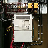
Control valves are used to control the flow of fluids by varying the size of the flow passage as directed by a signal from a controller. The valve is made up of three parts: the body, actuator, and positioner. The control valve body contains the modulating element and is where the fluid passes through. The modulating element comes in two main forms: sliding stem and rotary. Sliding stem elements, such as globe valves, have a steam and a seat. The stem sits in the seat and is connected to the actuator which drives it up and down. Rotary action elements, such as ball valves, sit in the seat at all times and rotate laterally while connected to the stem. Each rotary piece has a hole through the middle so as it rotates more of the opening is exposed and more fluid can flow through it.
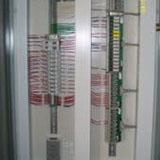
The actuator is attached to the top of the body, connects to the valve stem internally, and is what provides the motion of the valve. Actuators are driven by hydraulic, pneumatic, mechanical, or electrical sources; however most steam generator control valves will be electrically or pneumatically operated. The positioner is used to deliver pressurized air to the actuator in order to move the actuator to the correct set point. An analog I/P positioner is the most common style for modern control valve systems. The positioner reads a 4-20 mA electrical current signal (I) and converts it to a pneumatic pressure signal (P). This output signal then drives the actuator to the correct position.


Sliding Stem and Rotary Control Valves
Convection Section
Includes:
- Bare Tubes
- Convection Pressure Gauges
- Convection Side Covers
- Solid and Serrated Finned Tubes


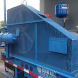
Convection Section Styles
The convection section is made up of the convection box and the tubes inside. The convection section is located in-between the radiant section and the exhaust stack and is used to capture heat from the exhaust gases and transfer that heat to the incoming feedwater before the water enters the radiant section. This increases the efficiency of the steam generator by reducing the amount of excess heat being exhausted to the atmosphere, and typically contributes 15-35% of the total absorbed heat for the steam generator. The convection box can come in a number of shapes and configurations, but the operating principle is the same for each style.


Bare, Solid, and Serrated Tubes

Inside the convection box are rows of bare and finned tubes that are used to transfer heat from the hot gas to the water inside the tubes. Hot combustion gas exits the radiant section and flows over an initial few rows of bare tubes (shock tubes). These bare tubes shield the finned tubes from direct radiant heat to protect the fins from the high temperatures of the entering gas. Without these tubes, the fins can get too hot and a portion of the fin tips can burn off. Finned tubes come in two basic styles: solid and serrated. Solid tubes are one solid long helically wrapped piece of metal around a circular pipe while serrated tubes have the same helically wrapped metal but the metal is separated to produce rows of rectangular fins.

Return Bend Ends

Tube Layout Styles
The ends of the tubes are all interconnected into one long coil using return bends, which are located on two sides of the convection box and are covered with removable doors. The doors are only removed in order to replace broken tubes or return bends. The rows of tubes can either be arranged in a staggered or inline layout. Staggered layouts shift over every other row so the tubes are between the rows below them, while inline layouts have all the rows aligned in straight rows vertically. Staggered layouts are more practical for steam generators because they required less space, and facilitate better contact time and turbulence for the exhaust gas passing through
Differential Pressure Transmitters
Differential pressure transmitters (DPT) measure the difference in pressure between two points and send an analog input signal back to the PLC. Each DPT used on a steam generator has three parts: the body, the manifold, and the orifice plate. The body of the DPT is where all the sensing takes place and is connected to the manifold. The manifold contains three valves and two vent plugs that are used during calibration of the device. Two tubes extend from the manifold into the flanges between which the orifice plate sits.
The orifice plate creates a drop in pressure which is read on both sides of the plate. Inside the body of the DPT is a diaphragm. This diaphragm will flex if there is any difference in pressure between the upstream and downstream sides of the orifice plate. This change is sensed by the DPT and is converted to an electrical signal via differential capacitance which is then sent back to the PLC. A higher flow of fluid creates a larger pressure drop and therefore a larger differential pressure. For gas and water this value is used when calculating and monitoring flow rate. For steam this value is used when calculating quality. See Orifice Plate for more information on orifice plates.
Differential Pressure Transmitter
Exhaust Stack
The exhaust stack is connected to the outlet of the Convection Section and is where all of the exhaust gas escapes the steam generator. The exhaust gas will mostly be made up of H2O, CO2, O2, and N2 and; after leaving the convection section, will be cooled to a few hundred degrees. Most steam generators will have a temperature transmitter and an O2 sensor on the back side of the exhaust stack for monitoring and adjustments.
The temperature of the exhaust gas is directly related to the flow and temperature of the water going through the convection piping. If the convection inlet temperature is too high then less water should be allowed to travel through the feed water pre-heater. This will lower the convection water inlet temperature and more heat will be transferred to the water in the convection section due to the larger starting temperature gradient. The opposite is true if the exhaust temperature is low. A high exhaust temperature indicates poor generator efficiency because any heat leaving the exhaust stack is a loss, but a low temperature could indicate that the convection section is producing condensation on the finned tubes and damaging them.
The O2 sensor measures the oxygen concentration in the exhaust stack which will ideally be 2-4%. Lower concentrations of O2 indicate that not enough excess air is being added for combustion. Not using enough excess air limits the combustion process since there are not enough oxygen atoms to favor the production of H2O and CO2. Higher concentrations indicate that too much excess air is being used which lowers the efficiency of the generator. Since air is mostly nitrogen and nitrogen is inert during combustion, having too much excess air means that extra energy is being used to heat the nitrogen present rather than being transferred to the water in the radiant pipes. The O2 sensor combats these problems by sending a signal back to the PLC. The controller then interprets what action is needed and sends a signal to the blower VFD so it can speed up or slow down the combustion blower.
Differential Pressure Transmitter

Oxygen Sensor
Learn More
Generator Components Section 1
- Air Compressor
- Atomization; Air and Steam
- Burner
- Check Valve
- Combustion Blower
- Control Valves
- Convection Section
- Differential Pressure Transmitters
- Exhaust Stack
Generator Components Section 2
- Feedwater
- Flue Gas Recirculation (FGR)
- Fuel Gas Main Train
- Fuel Gas Pilot Train
- Fuel Oil Train
- Generator Cab
- Generator Steam and Vent Valves
- Orifice Plate
- Quality Sample Condenser
Generator Components Section 3
- Radiant Section
- Refractory
- Safety Relief Valves
- Steam Separator
- Steam Traps
- TDS Meter
- Temperature Sensors
- Thermal Mass Meter
- Turbine Flow Meter
- U-Tube Manometer
- Water Softener