Generator Components Section 3
ACES Introduction to Generator Components
This section will provide an overview of functionality of components encountered throughout the steam generator. The information presented in this section is a general compilation of possible components on a steam generator. The appearance of many components depends on the style and setup of the generator.
Radiant Section
The radiant section is made up of the radiant shell and the tubes inside. The radiant section is located in-between the burner throat and the inlet to the convection section and is used to capture heat directly from the burner flame and transfer it to the incoming feedwater through radiant and conductive heat transfer. The radiant section typically contributes 65-85% of the total absorbed heat for the steam generator. Radiant heat transfer is electromagnetic radiation generated by the thermal motion of charged particles in matter. Radiation refers to the emission of energy in rays or waves, and heat moves through space as energy waves. As the flame burns, radiant heat is transferred to the exterior of the pipes lining the inside wall of the radiant section. This heat then penetrates the pipe wall through conduction and transfers the heat (energy) to the water inside.
Unlike with the convection section, none of the radiant section tubes are finned. Since the fins are thin metal to maximize surface area, being directly next to a high temperature open flame would overheat the fins and cause them to melt. This is the same reason why bare tubes are used as “shock tubes” at the inlet to the convection section. Hot water exits the convection section, passes through the bypass valve, and joins the water exiting the feedwater pre-heater before entering the radiant piping. As the water flows back and forth through the entire radiant coil, it will absorb heat and rise in temperature. Once the water reaches the saturation temperature for the pressure that it is under, it will start to vaporize and create a two-phase region of water and steam. The water will stay in two phases as long as the saturation temperature is maintained.


Radiant Section
The goal for most generators is to maintain saturation and produce a quality of 80%, meaning that 80% of the water has turned to steam and 20% remains as a liquid. If the temperature were to rise without the pressure also rising, the water would pass the saturation point and fully vaporize to create superheated steam. Superheated steam is extremely dangerous for a steam generator because steam carries an immense amount of thermal energy. This energy is transferred to the interior wall of the pipes, but the excess water in saturated steam helps to insulate and carry part of this heat away from the pipe walls. If superheated steam is formed, then there is no water barrier to carry away the excess heat and it is heavily transferred to the pipe walls which can cause them to overheat and burst. To prevent the tubes from overheating in this situation, there is a radiant tube temperature sensor installed on the radiant piping just before it exits the radiant section. This thermocouple measures the skin temperature of the pipe using a special welded tip. The tip looks like a metal rectangle welded to the outside of the pipe wall that is attached to a long probe that extends outside the radiant wall. There may also be a thermocouple of the same style directly on the pipe after it exits the radiant chamber.

Tube Skin Thermocouple
The radiant section will typically have a sight port, u-tube manometer, and manway on the burner end plate. The sight port allows operators to view the flame as well as monitor the overall condition of the tubes inside, the u-tube manometer measures the differential pressure of the radiant chamber, and the man way is a removable door that allows for maintenance to enter the radiant chamber.

Manway
Refractory
Refractory is any non-metallic material having chemical and physical properties suitable for withstanding continuous exposure to environments above 1,000 °F. Steam generators use two types of refractories; cast and fiber. Cast refractory is poured in a similar manner to concrete. It comes in bags of aggregate and is mixed with water to create semi-solid slurry. The slurry mixture is then poured and packed into a mold where it sets to dry and harden. Refractory anchors are welded to the base of the material where the refractory is being poured in order to give the refractory extra strength. This is similar to using rebar for concrete.

Cast and Module Refractory

Fiber refractory is similar to house wall insulation and comes in either sheets or modules. Sheets of refractory come in rolls that are cut to length and installed over stud anchors to keep them in place. In order to retain the most heat, sheets are typically stacked and pressed together to obtain a certain density of material. The alternative to fiber sheets is premade modules. These modules are layers of fiber sheets that are folded over each other to produce a certain density of material. A different style of stud is installed for modules, which looks like the threaded part of a bolt welded to a square base. The center of each module has a hole with a metal bracket on one side. The bracket goes over the stud and then a nut is screwed onto the bolt to hold the module in place. An H-anchor, or other reinforcement anchor, can be installed between modules to help hold them together.
As cast refractory heats up, it soaks in heat from the flame and retains this heat allowing for a more consistent temperature profile once the walls reach equilibrium. However, cast refractory is hard to replace if it becomes cracked or breaks. Because of this, cast refractory is typically only used in places where liquids may contact the refractory or where it is not practical to use fiber due to space restrictions. Cast refractory is commonly used on the convection section tubes sheets, the drip ledge directly under the burner throat in the radiant section, and on the floor of the radiant section for a drain pathway.


Cast and Fiber Sheet Anchors
Fiber refractory is used any place it can be easily installed due to its ease of replacement. If a portion of modules is destroyed, they can be individually replaced quickly reducing downtime and maintenance cost. Another advantage with using fiber overcast is that fiber does not require a soak time and heats the radiant much faster. However, fiber refractory is more prone to temperature fluctuations.

Fiber Modules

Safety Relief Valves
A safety relief valve, also known as a pressure relief or safety valve, is a type of safety device used to control or limit the pressure in a system which might otherwise build up and cause damage to the steam generator. The standard spring-loaded safety valve is a self-acting device consisting of a right angle pattern valve body with an inlet connection mounted on the pressure containing system.

Safety Relief Valves


During normal operation, a fluid or gas passes by the safety valve and fills only the inlet tract. The spring is set to a certain resistance which correlates to a pressure rating. As the pressure of the fluid reaches the maximum pressure allowed by the spring tension, the spring will contract and raise the disc off the seat, which increases the spring force. This means that the pressure would have to continue to rise before any further lift can occur and for there to be any significant flow through the valve. The additional pressure required before the valve discharges at its rated capacity is called the overpressure.
To open fully from this small overpressure, the disc typically has a shroud around it. As fluid begins to flow into the control chamber, the shroud creates a larger area for the fluid to push against. The shroud also redirects the fluid downward. The combined effects of these two factors overcompensate for the spring force as it contracts and allows the valve to open fully from a small over pressurization. Once the pressure in the system is reduced, there is not enough force to overcome the spring force and the valve closes itself. Safety relief valves will be located on the feedwater pump, the steam atomization knockout drum, and two will be on the steam line between the outlet of the radiant section and the generator pressure control valve. The two safety valves on the steam line are commonly on, or right before, the steam separator.

Relief Valve Working Principle
Steam Separator
The steam separator is located in between the exit of the radiant section and the steam DPT and is used for separating entrained water from wet steam to output 100% quality steam to the well. Water is an unwanted product when injecting a well and without a steam separator, both water and steam will enter the well. Water has a much lower enthalpy than steam at the same temperature and pressure, and for systems with a constant pressure, the heat absorbed and released is equal to the change in enthalpy. Since steam has a higher enthalpy than water, it is able to carry more heat to release into the well.

Steam Separator
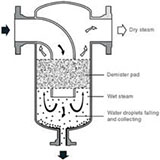
The three most common types of separators used are baffle, cyclonic, and coalescence separators. A baffle separator consists of several baffle plates which cause the steam to change direction as it passes through the separator body. The entrained water has a greater mass and inertia than the steam, thus, when there is a change in flow direction, the dry steam flows around the baffles and the water droplets collect on them. A cyclonic separator uses a series of fins to create a high-speed cyclonic flow. The velocity of the steam causes it to swirl around the body of the separator. This causes the heavier water droplets to fall out of suspension and hit the walls where they collect and flow to the drain. A coalescence separator forces the steam flow through a mesh pad, also called a demister pad. The demister catches the water droplets as steam flows through it. The droplets increase in size until they are too heavy and fall to the bottom of the separator.
The bottom of the separator will lead to a pipe with two valves. The first valve (quality sample line valve) will have a compression connection with metal tubing that goes to the steam inlet of the quality sample condenser. The second valve (blowdown valve) will have a short connection pipe and is used for purging the separator from buildup before the sample condenser line is opened. This is necessary because buildup in the separator piping could clog the quality sample line due to its small diameter.

Baffle, Cyclonic, and Coalescence Separators


Steam Traps
Steam traps are used to discharge condensate while retaining live steam in the system. This allows pure steam to flow through pipes and equipment. Without a steam trap, condensate droplets in the steam can cause poor heat transfer and damage to process equipment. There are three main types of steam traps: thermostatic, mechanical, and thermodynamic. Thermostatic steam traps work off of the temperature of the fluid. Inside the trap is a temperature sensing element. Initially as air and condensate flow through, the element is cooled and remains open. Once steam starts flowing and heats the element, it causes the valve inside to pull towards the seat and close off any flow. While the trap is closed, any condensate will accumulate around the element and cool it. Once the element is sufficiently cooled by condensate, it will open and drain.

Steam Separator

A mechanical steam trap has a float inside that raises and lowers to open the valve. As condensate accumulates inside the trap, the float will float on top of the water and rise with the level of the water present. Eventually the float will reach a point where it will open the valve and all the condensate will be drained. The body of the trap will then fill with steam and the float will drop down and close the valve since it cannot float on steam. The last and most common for steam generators is the thermodynamic trap, also sometimes referred to as a disc trap. Inside the thermodynamic trap is a disc that covers a hole in the outlet of the valve. Before steam is made, water and air force the disc up away from the hole and flow through the valve outlet. As steam is produced, it fills the cavity above the disc and pushes it down until the outlet hole is covered. Over time the inlet cavity will fill with condensate while the steam continues to apply a downward force on the disc. The steam in the chamber above the disc will eventually begin to cool and condense, at which point the upward force from the condensate will exceed the downward force on the disc and the disc will lift and drain the valve.

Baffle, Cyclonic, and Coalescence Separators
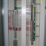
TDS Meter
A TDS meter (also called a conductivity meter) is used to measure the total dissolved solids (TDS) in a liquid. TDS is a combination of all organic and inorganic substances contained (dissolved) in a liquid in molecular, ionized, or micro-granular form. Solid sizes present are small enough to pass through the water filtration upstream of the generator which is used to reduce the hardness of the water. As water turns to steam the dissolved solids do not evaporate and instead stay in the remaining water in the system that has not vaporized. A sample of water is taken from the steam line and referenced against the inlet feedwater. Since the steam line is only now partially liquid water and all the dissolved solids are within the liquid, the concentration of dissolved solids is higher than in the inlet feedwater. Estimated steam quality can then be calculated from these two values.

TDS Meter
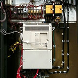
Temperature Sensors
Temperature sensors are used throughout the steam generator for helping to calculate flow rates and monitoring and protecting the generator from high temperature scenarios. Temperature sensors used can come in two different styles which include resistive temperature devices (RTDs) and thermocouples (TCs). A RTD measures the electrical resistance between metals whose resistance is a function of temperature. A thermocouple consists of two dissimilar metals joined at one end. When the junction of the two metals is heated or cooled a voltage is produced that can be correlated to temperature.

Temperature Sensor
Thermal Mass Meter
Thermal mass meters measure the flow rate of gases and liquids based off of the convective heat transfer properties of the fluid. These meters can be used as an alternative to using a PT, DPT, and TT to calculate the fuel gas flow rate. Each thermal mass meter contains a heat source with an RTD or other temperature sensor on both sides and measure the flow in one of two ways. The first is by introducing a constant amount of heat into the flowing stream and measuring the associated temperature change. The second is by maintaining a constant temperature difference between the sensors and measuring the heater energy that is required to do so.

Thermal Mass Meter
Thermal mass meters typically come in two styles: immersion and externally heated. Immersion heaters place the heat source and temperature sensors within the pipe and use the first measurement method described above. Externally heated thermal mass meters have the heat source and temperature sensors mounted to the outside of the pipe. This style is more commonly used for corrosive fluids and gases or fluids which would create a coating effect and inhibit correct measurement. However, mounting the sensors externally slows the response rate of the sensors and makes the measuring process nonlinear. This is because the heat introduced is distributed over a portion of the pipe’s surface and transferred to the process fluid at different rates along the length of the pipe.

Immersion and External Thermal Mass Meters

Turbine Flow Meter
A turbine flow meter is used to measure the volumetric flow of a fluid and is an alternative option to the coriolis meter for measuring fuel oil flow rate. As fluid flows through the turbine meter, it impinges upon the turbine blades that are free to rotate about an axis along the center line of the turbine housing. The angular velocity of the turbine meter is directly proportional to the fluid velocity.

Turbine Meter
U-Tube Manometer
On a steam generator a u-tube manometer is used to measure the radiant section air pressure directly after the burner and is located on the burner end plate. A u-tube manometer is a simple measuring device that functions on the displacement of a fluid due to an applied force. By design, the manometer is a single glass tube in a “u” shape that is typically filled with mercury, oil, or water. The fluid is filled to the zero line on the measuring template located in between the two tube sides. As the pressure raises or drops, it displaces one side of the fluid depending on whether the pressure is positive or negative (vacuum).

Manometer

Water Softener
Water softening is a process that removes minerals, such as calcium, magnesium, and lime; from water to reduce scale buildup in the steam generator. Without this process, water with high levels of calcium can clog the pipes with the buildup left behind as the water turns to steam. A water softener is made up of a series of control valves, mineral tanks, and a brine tank. The control valves are used to guide the water down the correct path as it passes through the mineral tanks. The mineral tanks which include a filter, a softener, and a polisher are filled with plastic beads commonly made of polystyrene. These beads create an ion-exchange column as they are negatively charged, and magnesium and calcium are positively charged. The brine tank contains a solution of water and either salt or potassium which is used to regenerate the beads in the mineral tanks.
The beads within the tanks originally contained a sodium ion bonded to the negatively charged beads. As water with magnesium and calcium passes through the beads, the monovalent sodium (Na+) cations are replaced (exchanged) with the divalent magnesium (Mg2+) and calcium (Ca2+) cations since the divalent cations bond more strongly. When all the available sodium ions have been replaced, the beads must be recharged by eluting the magnesium and calcium with the brine solution. The first tank (filter) is cleared only by reversing the flow of water while the other two tanks (softener and polisher) reverse the flow of water, but also pass the brine solution through them. Even though sodium is a weaker cation than magnesium and calcium, the high concentration in the brine solution allows the sodium to replace the magnesium and calcium on the beads. This solution is then flushed out of the tanks through a drain valve and the softening process restarts. Most industrial water softener systems will have at least two sets of mineral tanks and one brine tank. This allows three of the mineral tanks to be softening water while the other three are being regenerated allowing for no downtime.

Hard Water Scale
Learn More
Generator Components Section 1
- Air Compressor
- Atomization; Air and Steam
- Burner
- Check Valve
- Combustion Blower
- Control Valves
- Convection Section
- Differential Pressure Transmitters
- Exhaust Stack
Generator Components Section 2
- Feedwater
- Flue Gas Recirculation (FGR)
- Fuel Gas Main Train
- Fuel Gas Pilot Train
- Fuel Oil Train
- Generator Cab
- Generator Steam and Vent Valves
- Orifice Plate
- Quality Sample Condenser
Generator Components Section 3
- Radiant Section
- Refractory
- Safety Relief Valves
- Steam Separator
- Steam Traps
- TDS Meter
- Temperature Sensors
- Thermal Mass Meter
- Turbine Flow Meter
- U-Tube Manometer
- Water Softener