Oil Recovery
ACES Introduction to Oil Recovery
In 2022 the Global oil production amounted to 93.9 million barrels per day with a projected steady rise in production levels in the future due to newly emerging markets and technologies, and growing populations. However, nearly seven trillion barrels of basic and heavy oil will remain in reservoirs after conventional recovery methods have been exhausted. This has forced the introduction of new methods to improve oil in place (OIP) recovery (total oil content of a reservoir).
Oil Recovery Stages
The stages of oil recovery are broken down into three groups: primary, secondary, and tertiary recovery. These three recovery methods follow a natural progression of oil production until a point of low economical profitability is reached. The primary recovery stage of hydrocarbon production includes natural flow and artificial lift techniques. Initially, the reservoir pressure is considerably higher than the bottom pressure in the wellbore. This creates a high differential pressure which naturally drives the oil towards the well and up to the surface. As oil production continues, the differential pressure drops due to a decrease in reservoir pressure. It is at this point that an artificial lift system, such as a rod pump, is introduced to offset the difference. Once primary methods reach an uneconomical threshold, secondary methods are introduced.
The secondary recovery stage of hydrocarbon production includes flooding and pressure maintenance techniques. During the flooding stage, water and/or gas is injected into the reservoir through injection wells. The purpose of secondary recovery is to maintain reservoir pressure and to displace oils towards the wellbore. Gas is typically injected into the gas cap (the free space above the oil), while water is injected into the production zone to extract the oil. Once secondary methods reach an uneconomical threshold, or the injected fluid is being extracted in a considerable amount, tertiary methods are introduced.
The tertiary recovery stage of hydrocarbon production includes methods mainly utilizing thermal, gas injection, and chemical flooding techniques. This stage is synonymously referred to as enhanced oil recovery (EOR). This should not be confused with improved oil recovery (IOR), which is a more general term that implies improving oil recovery by any means.

Recovery Stages
Enhanced Oil Recovery

EOR for Different Hydrocarbons
EOR is more specific in concept than, and can be considered a subset of, IOR relating to tertiary recovery methods. EOR refers to a reduction in oil saturation below the residual oil saturation (Sor). Residual oil saturation is the ratio of the immobile residual oil volume divided by the effective porosity. Reduction in Sor is the only way to recover oils retained due to immobile high viscosities and oils retained due to capillary forces. Capillary forces represent the interfacial tension between two immiscible (non-mixing) fluid phases occupying the same space that must be overcome to initiate flow.
Residual oil mobilization is mainly influenced by two factors: capillary number (NC) and Mobility Ratio (M). The following two equations represent these two factors:


The dimensionless capillary number, also denoted Ca in some industries, is used in fluid flow to characterize the relative effect of viscous forces versus surface tension acting across an interface between a liquid and gas, or between two immiscible liquids. The most practical way of increasing the capillary number is by the application of heat. For a flowing fluid, if NC >> 1, then viscous forces dominate over interfacial forces; the opposite is true if NC << 1. Capillary numbers are relatively proportional to the speed of flow; capillary numbers are large for high-speed flow and small for low-speed flow. A typical reservoir capillary number is in the magnitude of ~10-6.
The dimensionless mobility ratio is a ratio of effective permeability to phase viscosity of an injected fluid divided by that of the fluid it is displacing. The mobility of the displacing fluid and oil is defined behind and ahead of the displacement front (interface between the two fluids), respectively. Mobility ratio influences both the microscopic (pore level) and macroscopic (areal and vertical) displacement efficiencies. A value of M >1 is considered unfavorable because it indicates that the displacing fluid flows more easily than the displaced fluid. This can result in some of the residual oil being bypassed and requires more displacing fluid to reach a given Sor, which lowers the efficiency and cost-effectiveness of the oil recovery system.
Thermal Recovery
Why Thermal Methods
Thermal methods for EOR have been studied since the 1950s, and are the most advanced among EOR methods when taking field success and technology advancements into account. Thermal recovery is best suited for heavy, viscous crude oils, and involves the introduction of thermal energy or heat into a reservoir to raise the temperature of the oil and reduce its viscosity, thus lowering the mobility ratio. In-situ combustion and steam injection are the most widely used forms of thermal recovery. In-situ combustion involves injecting air into the well and then igniting part of the oil to generate heat internally and produce combustion gases, which both enhance recovery. Steam injection is more widely practiced and is what ACES steam generators are used for.

Thermal Recovery Methods
Steam Injection Methods
Steam injection is the most common form of thermal injection and is comprised of three major styles: cyclic steam stimulation (CSS), steamflooding, and steam-assisted gravity drainage (SAGD). The steam injection method used is dependent upon the depth of the reservoir, the thermal properties of the surrounding formations, and the fluid properties of the in-place oil. These three methods are popular in the US, Canada, Venezuela, and Russia, among other countries.
Cyclic Steam Stimulation (CSS)
Cyclic steam stimulation, also known as the Huff and Puff method, is a ‘single well’ process consisting of three legs: steam injection, soaking, and production. This method is commonly used when reservoir oil is in the range of 10,000-50,000 centipoise (cP). The initial steam injection period can vary between a few days to weeks and consists of steam being directly injected into a well near the formation base. At this point the well pressure is typically greater than the fracture pressure, and steam extends into the reservoirs via gravity segregation. The well is then shut in for a few days for the soak period to allow heat distribution to occur between the steam and the oil. Lastly, the oil is pumped out of the reservoir over an extended period of time until the oil rate declines to an unprofitable margin, at which point the process is started over again. In high viscous reservoirs the first injection cycle is typically carried out for a shorter period of time than other cycles. This reduces the displacement of certain undesirable materials and increases the output of the subsequent few cycles.
During the onset of a production phase the oil recovery rate increases quickly due to high oil saturation, high increased reservoir pressure, and lower oil viscosity. As time progresses, the reservoir pressure decreases and the oil viscosity increases due to heat losses to the surrounding rock and fluids present in the reservoir. Different factors can influence the length of the production phase time such as the total soak time. If the soak time is too short, more heat is accumulated near the wellbore and is drawn in with the oil when the well is opened. If soak time is too long, heat losses occur in the overburden and underburden layers of rock within the reservoir.

CSS Method
Steamflooding Method
Steamflooding, or continuous steam injection, is a thermal recovery method that uses steam generated from above ground which is then injected into the reservoir through specially distributed injection wells. Steam moves throughout the reservoir until it condenses, thereby heating the reservoir oil and reducing its viscosity. The heat also distills light components of the oil, which condense in the oil bank ahead of the steam front, further reducing the oil viscosity. Gas drive of the highly mobilized oil is the principle oil recovery mechanism in this technique. The steam and condensed hot water generate this driving mechanism which draws the oil into the production wells.
Steamflooding is often applied in oil fields with relatively favorable geological conditions, lying at a shallow depth of 700-800 meters. The continuous injection of the steam creates a hydrodynamic connection between the injection well and the production well. However, steamflooding does have its drawbacks. In the past steamflooding has been considered an expensive EOR method due to its relatively long completion time and high operational expenses. Steam breakthrough, sand plugging, and overheating of wells have been known to occur during steamflooding. During breakthrough, steam creates unwanted channels that lower heat and oil recovery efficiency. Sand plugging occurs with the presence of steam turbulence. The steam detaches sand grains and carries them into the well perforations, which causes complications within the tubes. Lastly, an overheated well may have a tendency to negatively affect certain equipment used during the production phase.

Steamflooding Method
Steam-Assisted Gravity Drainage (SAGD)
Steam-assisted gravity drainage is used in areas with large deposits of heavy oil and bitumen, such as Alberta, Canada. This process relies on the gravity segregation of steam and consists of a pair of parallel horizontal wells that are placed 4-10 meters apart in the same vertical plane. The top well acts as the steam injector and the bottom well serves as the producer. Steam rises in an up and out pattern forming a steam chamber. This chamber mobilizes the oil, which drains down by gravity and is captured by the producer. Like steamflooding, SAGD is a continuous injection method.
The expanding steam chamber is characterized by two stages: ramp-up and plateau. During ramp-up the initial steam chamber growth happens in an upward direction that occurs much faster than the lateral growth due to the nature of heat to rise. The injection and production rates increase during this time. Once the chamber reaches the top of the reservoir formation, lateral growth takes over and production reaches a maximum (plateau) and slowly declines. Two basic driving mechanisms exist for SAGD: ceiling drainage and slope drainage. Ceiling drainage occurs when the steam chamber is rising and expanding and causes the oil to flow in a countercurrent pattern. Ceiling drainage plays a dominant role in the early stages of the process and is a function of vertical permeability. Slope drainage occurs when the steam chamber is expanding sideways horizontally and plays a more dominant role in the later stages of the process.

SAGD Method
Learn More

Generator Components Section 1
- Air Compressor
- Atomization; Air and Steam
- Burner
- Check Valve
- Combustion Blower
- Control Valves
- Convection Section
- Differential Pressure Transmitters
- Exhaust Stack
Generator Components Section 2
- Feedwater
- Flue Gas Recirculation (FGR)
- Fuel Gas Main Train
- Fuel Gas Pilot Train
- Fuel Oil Train
- Generator Cab
- Generator Steam and Vent Valves
- Orifice Plate
- Quality Sample Condenser
Generator Components Section 3
- Radiant Section
- Refractory
- Safety Relief Valves
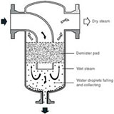
- Steam Separator
- Steam Traps
- TDS Meter
- Temperature Sensors
- Thermal Mass Meter
- Turbine Flow Meter
- U-Tube Manometer
- Water Softener